Use the Input Node to configure simulation parameters programmatically. Many simulation algorithms ie.
2
This is a complete list of Labview tutorials.

. Use the LabVIEW Simulation Interface Toolkit to. MacOS and Linux Launch LabVIEW and select HelpControl Design and Simulation Module to launch the LabVIEW Control Design and Simulation Module Help. On some systems the media mounts automatically.
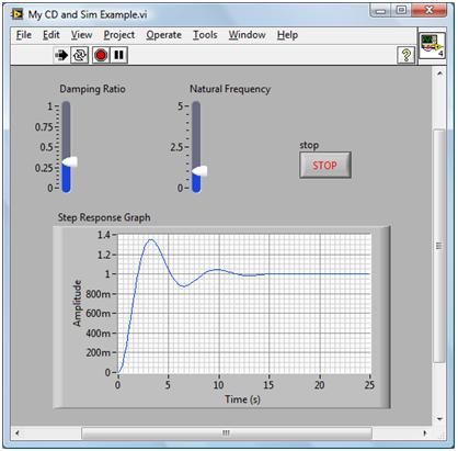
LabVIEW is produced by National Instruments It is assumed that you have basic. A second order system is used to introduce the use of the software for analysis and simulation of a simple system. LabView Control Design and Simulation Module.
Considerations for Embedded Targets. A valid license for the NI LabVIEW Control Design Simulation Module from National Instruments is needed. In the control loop the motor is the plant and a mathematical model or transfer function that describes its behavior must be modeled using MathScript.
Lessard Chapter Part of the Synthesis Lectures on Biomedical Engineering book series SLBE Abstract LabVIEW which stands for Laboratory Virtual Instrumentation Engineering Workbench is a graphical computing environment for instrumentation system design and signal processing. Tutorial You will find all the required instructions in the following documents. The exported model is integrated with LabVIEW utilizing the NI External Model Interface.
Control and Simulation in LabVIEW The Control Simulation Loop has an Input Node upper left corner and an Output Node upper right corner. Labview can be interfaced with Arduino and other microcontrollers to receive data through serial communication. LabVIEW Control Design and Simulation Exercise Charles S.
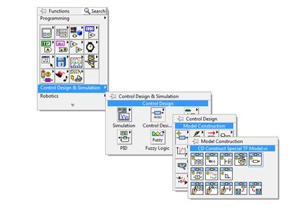
In this Tutorial we will need the following sub palettes in the Control Design and Simulation palette. This tutorial provides an introduction to the LabVIEW Control Design and Simulation Module and its use with the LabVIEW MathScript RT Module. You can use models created in Control Design Toolkit in a Simulation diagram in the LabVIEW Simulation Module.
Building and Configuring Simulations. The Simulation Module adds. Numerical methods for solving the underlying differential equations are available eg.
Refer to the LabVIEW Control Design User Manual for conceptual information about using the control design functionality of the Control Design and Simulation Module. Use the Input Node to configure simulation parameters programmatically. LabVIEW Simulation Module1is a block diagram based environment for simulation of linear and nonlinear continuous-time and discrete-time dynamic systems.
Control system analysis and simulation 1 Preface This document gives an introduction to the Control Design Toolkit version 20 for LabVIEW 71. Converting a Control Design Toolkit model to a Simulation Module model. Labview can also be used to program Arduino.
Ad Learn LabVIEW online at your own pace. Build powerful user interfaces for models developed in the Simulink environment and deploy them to real-time hardware with LabVIEW. In addition to the topics contained in this help file the LabVIEW Control Design User Manual contains information about using LabVIEW to design analyze and deploy controllers for dynamic systems.
Join millions of learners from around the world already learning on Udemy. You also can configure these parameters interactively using the Configure Simulation Parameters dialog box. This interface has the following limitations.
However it is then necessary to first convert the model by using the CD Convert Control Design to Simulation function. Parameters inputs outputs must not exceed 25. If you are new to the Control Design and Simulation Module consider completing the Getting Started with Simulation tutorial.
Control and Simulation in LabVIEW The Control Simulation Loop has an Input Node upper left corner and an Output Node upper right corner. Use mount mntcdrom to mount the media. Only one discrete sample time is supported.
Complete the following steps to install the Control Design and Simulation Module on Linux. By using the LabVIEW Control Design and Simulation Module together with the LabVIEW MathScript Module users can design model and simulate a DC-control system. You also can configure these parameters interactively using the Configure Simulation Parameters dialog box.
Ad Learn LabVIEW online at your own pace. The LabVIEW Control Design and Simulation Module is add-on software that integrates with the LabVIEW programming environment to offer capabilities such as built-in parallelism multicore and multirate technologies as well as tools for deploying to real-time hardware. Labview tutorials and projects have many applications in electrical project electronics projects and embedded systems projects.
Ordinary Differential Equation Solvers. Getting Started with Simulation. Hardware To follow this tutorial completely you will need the device NI ELVIS I.
Control Simulation Tutoriapdf Updated Exercise Instructionspdf. Select the template Blank VI and click Finish. Log into the system as root.
Start today and improve your skills. A LabVIEW Control Design and Simulation Module 1 National Instruments With the NI LabVIEW Control Design and Simulation Module you can simulate dynamic systems design sophisticated. Insert the Control Design and Simulation Module installation media.
Control Design and Simulation Module. The goal of this tutorial is to use the LabVIEW Control Design and Simulation Module to view the position x t of the mass m with respect to time t.

Basics Of Control Design And Simulation Ni
Labview Control Design And Simulation 4 Configuring Up A Simulation Loop Properly Youtube
Basics Of Control Design And Simulation Ni
Types Of Simulation Subsystems Control Design And Simulation Module Labview Control Design And Simulation Module Documentation

Basics Of Control Design And Simulation Ni
2
Basics Of Control Design And Simulation Ni
Types Of Simulation Subsystems Control Design And Simulation Module Labview Control Design And Simulation Module Documentation
0 comments
Post a Comment